Steering Reducer
The salvage motor spins fast and weak; the steering column needs the opposite — slow and strong. The reducer trades the motor's cheap speed for torque. See Sizing the actuator for why (torque is heat-limited, speed is basically free) and the numbers (~8 Nm at the column, ~47 W, ~11:1 reduction).
Why a planetary
We needed ~11:1 in a small, coaxial package, cheap enough to reprint when it breaks, and backdrivable (so the wheels still turn by hand if the electronics die). A planetary packs the whole reduction into one ring of gears around the shaft — coaxial and compact, load shared across the planets, and it stays backdrivable.
The other reducer types either don't backdrive (worm, ball-screw), can't be printed with any strength (harmonic flexspline), or sprawl across two axes (plain gear train). Full comparison and the two alternatives we're keeping live: Alternative reducer designs.
The price of the planetary is that it's the least forgiving of print error — every planet has to mesh the sun and the ring simultaneously, so all the tolerances have to agree at once. That's the source of most of the failures below.
Current design (~11:1, two stages)
| Stage | Type | Teeth | Module | Centre distance | Ratio |
|---|---|---|---|---|---|
| 1 — planetary | sun → 4 planets → fixed ring | sun 12, planet 16, ring 44 | 2 mm | 28 mm | 4.67 : 1 |
| 2 — output pair | pinion → big gear (to column) | pinion 13, gear 31 | 3 mm | 66 mm | 2.38 : 1 |
| Total | ≈ 11.1 : 1 |
All three planetary gears share module 2 mm, 20° pressure angle. The geometry isn't free: an internal planetary obeys Z_ring = Z_sun + 2·Z_planet (44 = 12 + 2·16), so fixing the ring at 44 and the sun at 12 forces the planet to 16 and the centre distance to m·(Z_sun + Z_planet)/2 = 28 mm. The ratio is 1 + Z_ring/Z_sun = 4.67 (fixed ring, sun input, carrier output).
The planetary was 5.4:1 with a 10-tooth sun; it dropped to 4.67:1 when the sun/planets moved to the Norelem hub geometry (12-tooth sun, off-the-shelf steel option). Full Fusion parameters live in the team's kart/steering/ files (planetary_reducer_parameters.md, output_pinion_parameters.md).
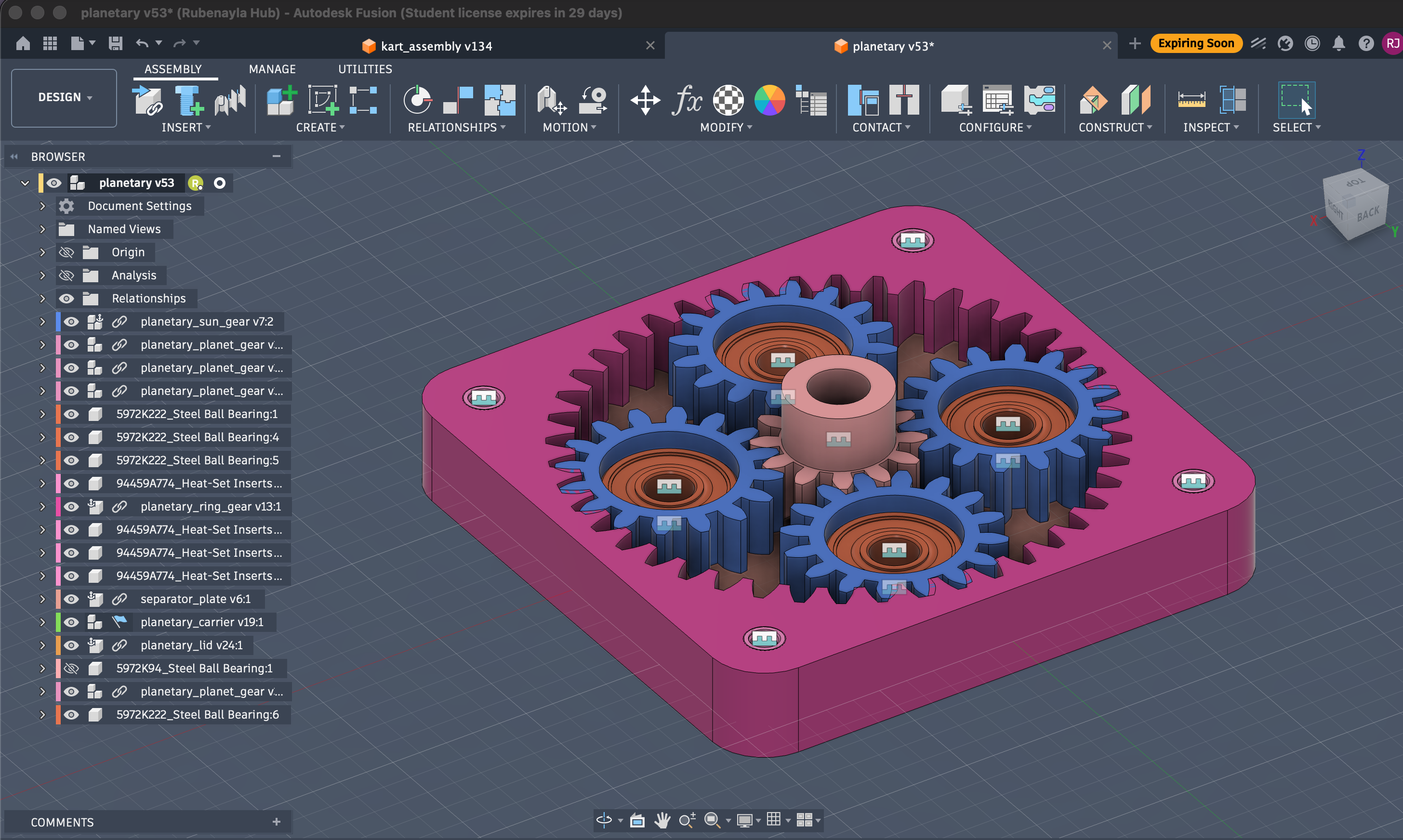
The current planetary (Fusion planetary v53): 12-tooth sun at centre, 4 planets, 44-tooth ring.
The planets ride on the carrier (the output); the sun is the motor input and the ring is held fixed:
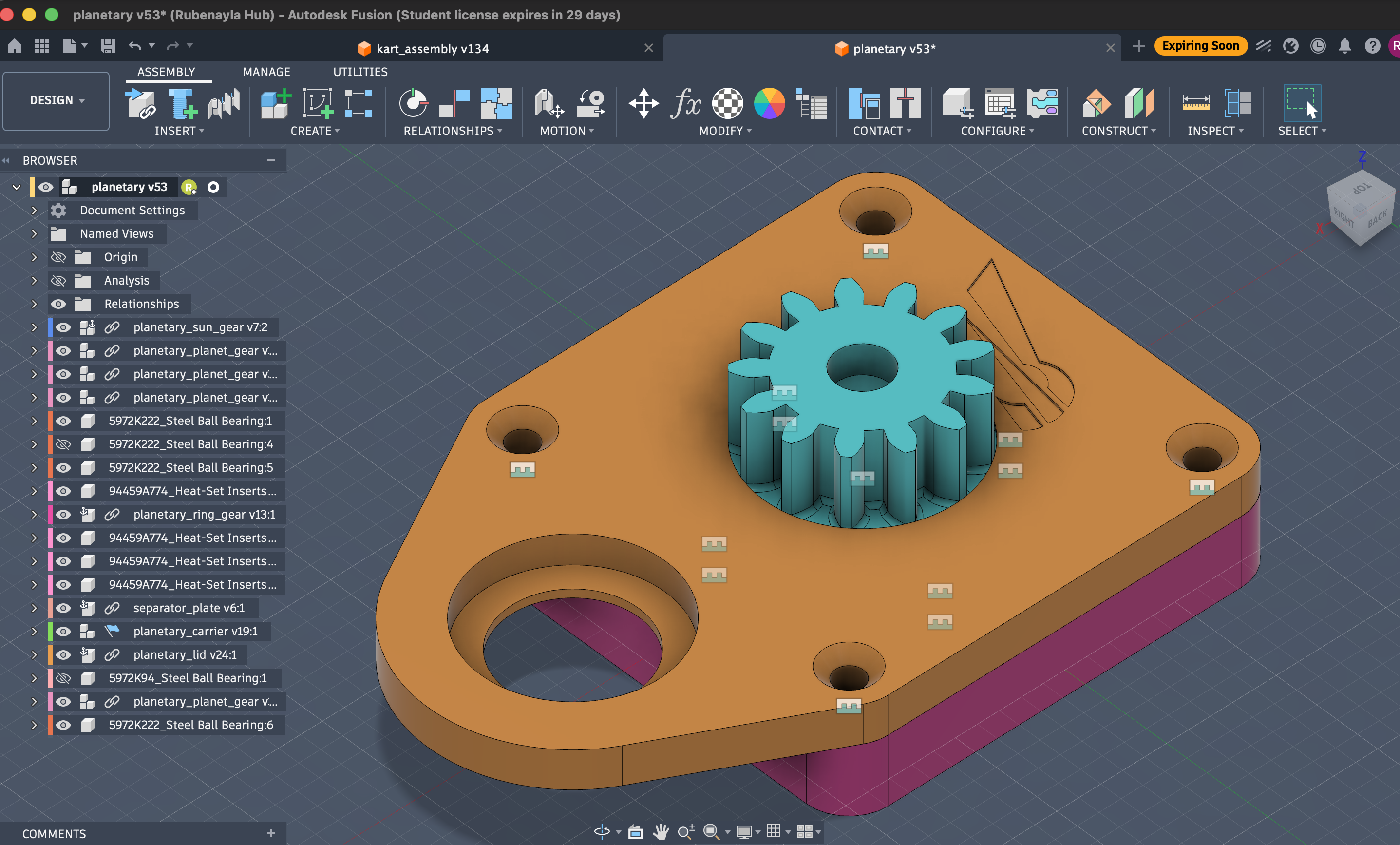
Carrier plate with the sun gear — the carrier clamps to the motor shaft and carries the four planets on steel ball bearings.
Gear generation
The gear tooth profiles are generated in Fusion 360 with the GF Gear Generator plugin, one part file per gear, referencing the shared module / teeth / pressure-angle parameters. Two gotchas worth knowing:
- The generator needs a Hybrid Design file type — Part Design refuses to add the gear component.
- The generated teeth are static geometry, not parametric — changing a tooth-count parameter does not re-cut the teeth. Each gear has to be regenerated when its tooth count changes (and the circular-pattern count is hard-set, so bumping the parameter alone leaves stale geometry — a trap that has bitten us). Promote module / teeth / face width to user parameters so downstream features still update.
Gear materials — the real problem
Choosing a gear material isn't picking "the best" one; it's deciding what to optimise — every property trades against another:
low friction ↔ creep resistance ↔ rigidity ↔ wear ↔ toughness (not brittle) ↔ printability ↔ cost
| Material | Why considered | Why it fell short |
|---|---|---|
| PLA | stiff, trivial to print | brittle → poor fatigue; teeth snap, gears split. Broke after 5 laps. Fine only for the big, low-stress gears. |
| ABS | tougher than PLA, more heat, easy + cheap | not slippery, still creeps — but with the steel sun taking the D-flat load, it's good enough. This is the current printed material for the planets and carrier. |
| Nylon (PA) | low friction, tough — the classic gear plastic | creeps under sustained load → the D-flat on the motor shaft rounds off and slips. Absorbs moisture. |
| PPA | aromatic-ring nylon: stiffer, far less creep, low moisture | the step up; harder + dimensionally stable, better wear under load. |
| PPA-CF | carbon adds stiffness | CF is abrasive (wears the steel it grips) and embrittles → can worsen the cracking it's meant to fix. Test before committing. |
| Brass / steel | the endgame for the part that matters | machined / off-the-shelf (Norelem hub sun); no plastic wins at the motor interface. |
The root cause: the D-flat, not the gears
The real weak point is the motor-shaft interface — a D-flat + set screw in a creeping plastic. Fix the material there (brass / Norelem steel sun) and the root failure goes away regardless of what the rest is printed in. This is also why a cycloidal drive wouldn't dodge it — its eccentric input mounts on the same D-flat.
Failure modes seen
- PLA — brittle fracture: snapped teeth, gears split, within minutes of load.
- Nylon — D-flat creep (the flat rounds off → slip); teeth round off under sustained load.
- Holder / carrier deformation — the mount flexing under load lets the gears separate and skip; a failure path independent of the gears themselves.
Status: still iterating
Six print generations in, it works — kind of. Current path: a Norelem steel hub sun for the D-flat (the real failure point), the planets and carrier printed in ABS, and watching the carrier stiffness. PPA / PPA-CF were weighed for the printed gears but not adopted — ABS is tough enough once the steel sun carries the D-flat load. Not solved.
CAD
CAD available on request
The reducer is fully modelled in Fusion 360 — the parametric design, a STEP, and print-ready gear STLs. We haven't published the files here yet, but we're happy to share them: if you'd like the CAD for your own build, get in touch.