Legacy wiring (classic ESP32)
Temporary page — classic ESP32 hand-wired in the kart
This page documents the current hand-wired classic-ESP32 setup physically installed in the kart. No PCB — flying wires to an ESP32-DevKitC V4.
The project is moving to an ESP32-S3 based interface PCB (Kart Medulla (ESP32-S3)). Once that board is manufactured, flashed, and deployed, this page will be removed. Any rework on the classic setup should be minimal — only what's needed to keep the current kart running until the new board lands.
The Kart Medulla (legacy) uses the ESP32-DevKitC V4 (38-pin, USB-C) with an ESP32-WROOM-32D module. The 30-pin ESP32 board used earlier is deprecated and should not be used.
Firmware repository: UM-Driverless/kart-medulla
Classic ESP32 Overview
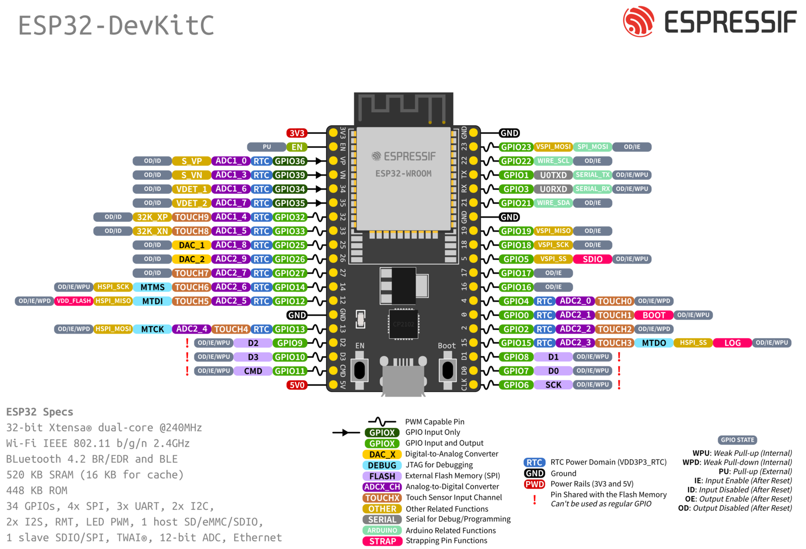
- CPU: Xtensa dual-core 32-bit LX6, up to 240 MHz
- Flash Memory: Up to 16 MB
- SRAM: 520 KB
- GPIOs: 34
- ADCs: 18-channel, 12-bit
- DACs: 2-channel, 8-bit
- Communication Interfaces: SPI, I2C, UART, CAN, I2S
Classic ESP32 Pin Assignment
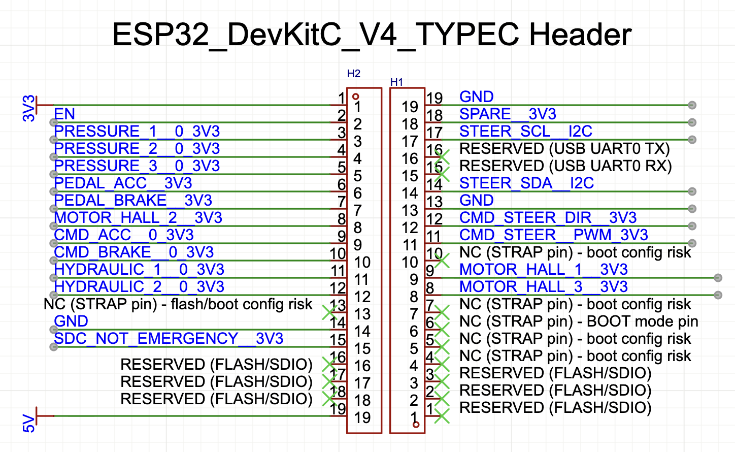
Complete pin map for the ESP32-DevKitC V4 (38-pin, USB-C) as wired in the current kart. Ordered by physical position on the board. H1 is the left header, H2 is the right header (19 pins each).
| Pin | Header | GPIO | Signal | Type | Notes |
|---|---|---|---|---|---|
| 1 | H1.1 | 6 | RESERVED | - | FLASH/SDIO |
| 2 | H1.2 | 7 | RESERVED | - | FLASH/SDIO |
| 3 | H1.3 | 8 | RESERVED | - | FLASH/SDIO |
| 4 | H1.4 | 15 | NC | - | STRAP pin (boot config risk) |
| 5 | H1.5 | 2 | STATUS_LED | Digital Out | Onboard LED (strap pin, keep LOW at boot) |
| 6 | H1.6 | 0 | NC | - | STRAP pin (BOOT mode) |
| 7 | H1.7 | 4 | NC | - | STRAP pin (boot config risk) |
| 8 | H1.8 | 16 | MOTOR_HALL_3 | Digital In | Motor hall sensor 3 (also UART2 RX) |
| 9 | H1.9 | 17 | MOTOR_HALL_1 | Digital In | Motor hall sensor 1 (also UART2 TX) |
| 10 | H1.10 | 5 | NC | - | STRAP pin (boot config risk) |
| 11 | H1.11 | 18 | CMD_STEER_PWM | LEDC PWM | Steering motor PWM (Cytron H-bridge) |
| 12 | H1.12 | 19 | CMD_STEER_DIR | Digital Out | Steering motor direction (Cytron H-bridge) |
| 13 | H1.13 | - | GND | Power | Ground |
| 14 | H1.14 | 21 | I2C_SDA | I2C | AS5600 steering angle sensor data |
| 15 | H1.15 | 3 | USB_UART_RX | UART0 RX | Reserved (binary protocol from Orin) |
| 16 | H1.16 | 1 | USB_UART_TX | UART0 TX | Reserved (binary protocol to Orin) |
| 17 | H1.17 | 22 | I2C_SCL | I2C | AS5600 steering angle sensor clock |
| 18 | H1.18 | 23 | SPARE | - | Available |
| 19 | H1.19 | - | GND | Power | Ground |
| 20 | H2.1 | - | 3V3 | Power | 3.3V supply |
| 21 | H2.2 | - | EN | Reset | Active-low reset |
| 22 | H2.3 | 36 (VP) | PRESSURE_1 | ADC1_CH0 | Pressure sensor 1 (input only) |
| 23 | H2.4 | 39 (VN) | PRESSURE_2 | ADC1_CH3 | Pressure sensor 2 (input only) |
| 24 | H2.5 | 34 | PRESSURE_3 | ADC1_CH6 | Pressure sensor 3 (input only) |
| 25 | H2.6 | 35 | PEDAL_ACC | ADC1_CH7 | Accelerator pedal (input only) |
| 26 | H2.7 | 32 | PEDAL_BRAKE | ADC1_CH4 | Brake pedal |
| 27 | H2.8 | 33 | MOTOR_HALL_2 | Digital In | Motor hall sensor 2 |
| 28 | H2.9 | 25 | CMD_ACC | DAC1 | Throttle analog output (0-255) |
| 29 | H2.10 | 26 | CMD_BRAKE | DAC2 | Brake analog output (0-255) |
| 30 | H2.11 | 27 | HYDRAULIC_1 | ADC2_CH7 | Hydraulic pressure sensor 1 |
| 31 | H2.12 | 14 | HYDRAULIC_2 | ADC2_CH6 | Hydraulic pressure sensor 2 |
| 32 | H2.13 | 12 | NC | - | STRAP pin (flash/boot risk) |
| 33 | H2.14 | - | GND | Power | Ground |
| 34 | H2.15 | 13 | SDC_NOT_EMERGENCY | Digital In | Shutdown circuit emergency status |
| 35 | H2.16 | 9 | RESERVED | - | FLASH/SDIO |
| 36 | H2.17 | 10 | RESERVED | - | FLASH/SDIO |
| 37 | H2.18 | 11 | RESERVED | - | FLASH/SDIO |
| 38 | H2.19 | - | 5V | Power | 5V supply |
GPIO 17/16 Conflict
GPIO 17 and 16 are used for MOTOR_HALL_1 and MOTOR_HALL_3. These are also UART2 TX/RX pins. When both halls are connected, UART2 debug logging is not available.
GPIO Restrictions
GPIO 6-11 are connected to SPI flash and must not be used. GPIO 34-39 are input-only.
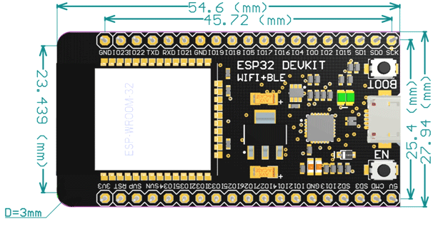
ESP32-DevKitC Dimensions